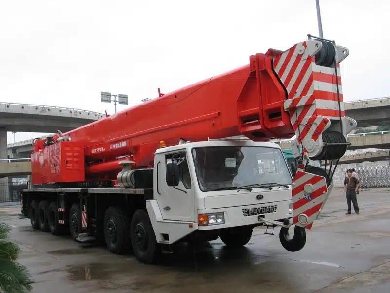
As a core hoisting equipment in engineering construction, the operational safety of mobile cranes (truck cranes) is directly related to personnel safety, equipment property and project progress. Among them, safety protection devices are the core components to avoid risks such as hoisting overload and instability. Reasonable selection and standardized installation are the keys to ensuring the compliant operation of equipment and preventing safety accidents. This article details the selection logic, core functions and installation requirements for the core safety protection devices of truck cranes, providing professional reference for industry practitioners.
I. Core Selection Basis for Core Safety Protection Devices
Truck cranes are equipped with a hoisting mechanism and a luffing and telescopic boom. Their rated lifting capacity is dynamically adjusted with the change of boom angle and boom telescoping (following the principle of moment balance). Relying solely on manual judgment is prone to overload and instability risks. Therefore, it is necessary to configure a moment limiter system that meets national standard requirements to achieve real-time monitoring, early warning and protection.
(1) Torque limiter instrument selection
The torque limiter is the “brain” of automobile crane safety protection. Its core role is to collect and calculate key parameters in lifting operations in real time. When it approaches or reaches the safety limit, it automatically issues sound and light warnings, and at the same time cuts off the dangerous actions (lifting, arm extension) control loop to prevent overload operations.
-
Instrument type selection: Since truck cranes need to dynamically monitor the impact of boom angle and boom length changes on the rated lifting capacity, adynamic moment limiter, Instead of ordinary weight limiters, to ensure that the safety status can be accurately judged based on real-time torque changes.
-
Instrument model selection: Combined with the needs of automobile crane operations, it is necessary to monitor three types of core signals at the same time-lifting weight signal, lifting arm angle signal, lifting arm length signal, so the instrument model needs to choose WTL-A (200) and above specifications, this series of instruments supports multi-signal synchronous acquisition, real-time operation, and strong anti-interference., Clear display, sensitive early warning and other advantages, suitable for all kinds of large and medium-sized automobile crane operation scenarios.
(2) Weight sensor selection specification
The weight sensor is the “sensing organ” of the torque limiter. Its core role is to accurately collect the actual weight of the lifting heavy object, convert the weight signal into an electrical signal and transmit it to the instrument, and provide core data support for torque calculation. The rationality of its selection directly determines the monitoring accuracy of the torque limiter.
-
Sensor model selection: At present, the SHL series is preferred for the weight sensors of this type of car crane. This series of sensors has the characteristics of impact resistance, waterproof and dustproof, and high accuracy (error ≤±0.5%). It is suitable for the complex outdoor operating environment of car cranes and can operate stably for a long time.
-
Sensor range determination: The selection of the range needs to be combined with the maximum rated lifting weight of the car crane and the magnification of the pulley. The core principle is “the range covers the maximum actual lifting weight while retaining reasonable redundancy.” Because it involves the calculation of the force of multiple sets of pulleys, there is no need for customers to calculate by themselves. The sales staff only need to confirm the two core parameters of the maximum rated lifting weight of the equipment and the pulley magnification to the customer, so that the corresponding range of SHL series sensors can be accurately matched to avoid insufficient accuracy due to excessive range and damage to the sensor due to excessive range.The problem.
(3) Angle/length gauge selection and direction judgment
The angle/length gauge is the “auxiliary sensing component” of the torque limiter. Its core role is to collect the pitch angle and telescopic length of the lifting arm in real time, and calculate it in conjunction with the weight signal to accurately obtain the actual torque under the current operating conditions to ensure the dynamic monitoring accuracy of the torque limiter, so the car crane mustSupporting the installation of angle/length measuring instrument.
-
Installation direction judgment:The core purpose of direction judgment is to ensure the accuracy of the data collected by the angle/length gauge and avoid monitoring deviations due to incorrect installation direction. Judgment method: Observe from the rear of the car crane toward the top of the lifting arm. If the cab is located on the left side of the lifting arm, it is the left installation; if the cab is located on the right side of the lifting arm, it is the right installation. When installing, it must be fixed strictly in accordance with the judgment result to ensure that the sensor is synchronized with the trajectory of the lifting arm.
-
Supporting requirements: When selecting the type, it is necessary to ensure that the angle/length measuring instrument is compatible with the torque limiter instrument. At the same time, customers are required to provide a working curve table of the lifting arm of the equipment to facilitate the calibration of the instrument parameters and ensure the accuracy of torque calculation at different angles and under different arm length working conditions, in line with the "Lifting Machinery Safety Regulations" (GB 6067.1-2010) Requirements.
(4) Signal line selection and length determination
The signal line is the “transmission link” between various types of sensors and torque limiter instruments. Its core role is to stably transmit electrical signals such as weight, angle, and arm length, so as to avoid signal interference or transmission interruption leading to equipment misjudgment and failure.
The length of the signal line needs to be determined according to the actual installation location of the sensor and the instrument. It is recommended that the customer provide equipment installation drawings or on-site measurement data to ensure that the length of the signal line is adapted to avoid signal attenuation caused by too long and installation difficulties caused by too short. At the same time, anti-interference shielded signal lines need to be selected to reduce the influence of electromagnetic, vibration and other factors on signal transmission in outdoor operations and ensure stable data transmission.
2. Precautions for core installation
-
The angle/length gauge needs to be installed at the root or middle of the lifting arm to ensure synchronous pitch and expansion with the lifting arm, and the mounting surface needs to be flat and firm to avoid vibration that causes the sensor to shift and affects the accuracy of data acquisition.
-
The weight sensor needs to be installed in the force part of the hook or pulley block to ensure uniform force on the sensor and avoid lateral force. At the same time, it is waterproof, dustproof, and anti-collision protection to adapt to the outdoor operating environment.
-
The torque limiter instrument needs to be installed inside the cab to facilitate the operator to observe the operating parameters (lifting weight, angle, arm length, torque value) in real time. The installation location needs to avoid direct sunlight and vibration interference to ensure the normal operation of the instrument.
-
All signal line laying needs to be standardized, avoid moving parts and sharp edges and corners of the equipment, do a good job of fixing and protection, avoid signal interruption caused by wear and tear during operation, and at the same time do a good job of grounding to improve the anti-interference ability.
-
After the equipment is installed, it is necessary to calibrate the parameters of the torque limiter in combination with the working curve table provided by the customer to simulate the operating scenarios under different working conditions to ensure that the early warning value and cutting action are accurate and reliable, and meet the requirements of safe operation of the equipment.
3. Summary
The safe operation of mobile cranes (car cranes) is inseparable from the reasonable selection and standardized installation of core safety protection devices such as torque limiters, weight sensors, angle/length gauges, etc. The core points are summarized as follows:
-
Due to the dynamic changes in the length and angle of the automobile boom, a dynamic torque limiter (WTL-A (200) and above models) must be selected, and SHL series weight sensors must be equipped to ensure synchronous monitoring of multiple parameters.
-
The angle/length gauge is a required part. The left-mounted/right-mounted direction needs to be accurately determined before installation, and the parameter calibration needs to be completed in combination with the working curve table after installation.
-
The signal line needs to be selected with anti-interference shielding type, and the length is determined according to the actual installation location to ensure stable signal transmission; the installation of all components must meet the requirements of the national standard to avoid safety risks caused by installation deviations.
Standardized selection, scientific installation, and regular calibration are the keys to playing the role of safety protection devices, which can not only ensure the safety of lifting operations, but also extend the service life of equipment and help the project advance efficiently.