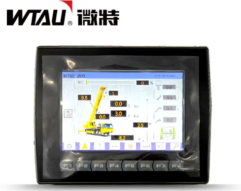
WTL-A710 Hydraulic torque limiterIt is an intelligent safety system tailor-made for wheeled cranes (such as truck cranes, tire cranes, etc.). "ThroughReal-time monitoring of hydraulic pipeline pressureBased on the data of the boom Angle and length, the working moment value is dynamically calculated. When the load approaches the critical value, the system automatically triggers an audible and visual alarm and cuts off dangerous operations, completely eliminating the risk of overloading and overturning of the hydraulic power take-off crane.
2. Main functions
Dual core of hydraulic perception and intelligent protection
Five-channel oil pressure precise monitoring
Synchronous monitoring of the main hook/auxiliary hook lifting oil circuit, luffing cylinder, rotary motor and hoisting system
Triple safety protection mechanism
→ Warning: Low-frequency buzzer alert
→ Slow down: Automatically limit the movement speed
→ Cut off: Immediately cut off the power output
Pre-diagnosis of equipment health
When the oil pressure fluctuates abnormally, the fault code is automatically recorded (such as leakage inside the main valve, pipeline blockage).
3. Scope of application
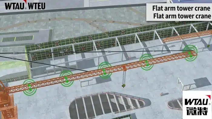
Full coverage of mobile hydraulic cranes
Typical equipment adaptation
► Automobile craneAnti-vibration design throughout the entire section (especially for rough construction sites)
► Marine deck craneSalt spray protective coating
► Pipeline construction machineryIt is powered by a wide DC voltage range of 12 to 36V
Harsh working condition verification
In Mohe, it starts up at an extremely cold temperature of -40℃; in Hainan, it operates continuously at a high temperature of 70℃
4. Configuration Instructions
The three major modules work in coordination
① Hydraulic sensor group
ModelWT-YY-01 (a total of 8 are required)
Key features4-20mA current signal output: freeze-thaw cycle tolerance from -30℃ to 70℃
Key points of deploymentEach oil pressure channel corresponds to an independent sensor (main hook/auxiliary hook/amplitude/rotation/hoist ×2).
② Signal conversion center
Core competenceSimultaneously process 8 channels of hydraulic signals
Protection Grade: IP65 metal sealed housing, wide temperature range for operation from -30℃ to 70℃
Linkage mechanismReal-time comparison of the oil pressure - Angle - length data chain
③ Customized software for working conditions
Core valueTorque generation algorithm based on the crane load curve
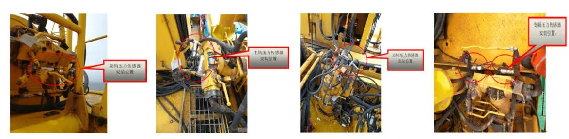
5. Installation specifications
Iron law for positioning hydraulic measurement points
Main hook pressure sensor
Installation position: Main hoist motor high-pressure oil pipe (bypass three-way interface)
Warning: The arrow indicating the direction of the oil flow must be aligned with the direction of the system flow
Auxiliary hook pressure sensor
Installation position: Oil circuit at the outlet of the auxiliary hoist balance valve
Key points: Keep a distance of more than 15cm from the valve (to avoid turbulent interference)
Amplitude pressure sensor
Installation position: Oil inlet pipe of the rodless cavity of the amplitude transformer cylinder (near the end of the cylinder)
Key point: The wire needs to reserve the bending allowance for the boom
Rotary pressure sensor
Installation position: Make-up oil pipeline for the rotary motor
→ Tip: Secure with metal clamps to prevent vibration and detachment
Dual sensors for the winch system
→ Positioning: One main and one auxiliary hoist high-pressure pipeline each (not interchangeable)
Construction red lineAll measurement points must be executed after installation50Bar holding pressure testMake sure there is no leakage before powering on
Maintenance Instructions
Oil product compatibilityOnly ISO VG46 hydraulic oil (viscosity error ±10%) is allowed.
Calibration cycleTighten the bolts 48 hours after the first use. Calibrate the oil pressure zero point every six months
Fault traceabilityA buzzer with three long and two short sounds indicates a clogged oil passage (the filter element needs to be checked).