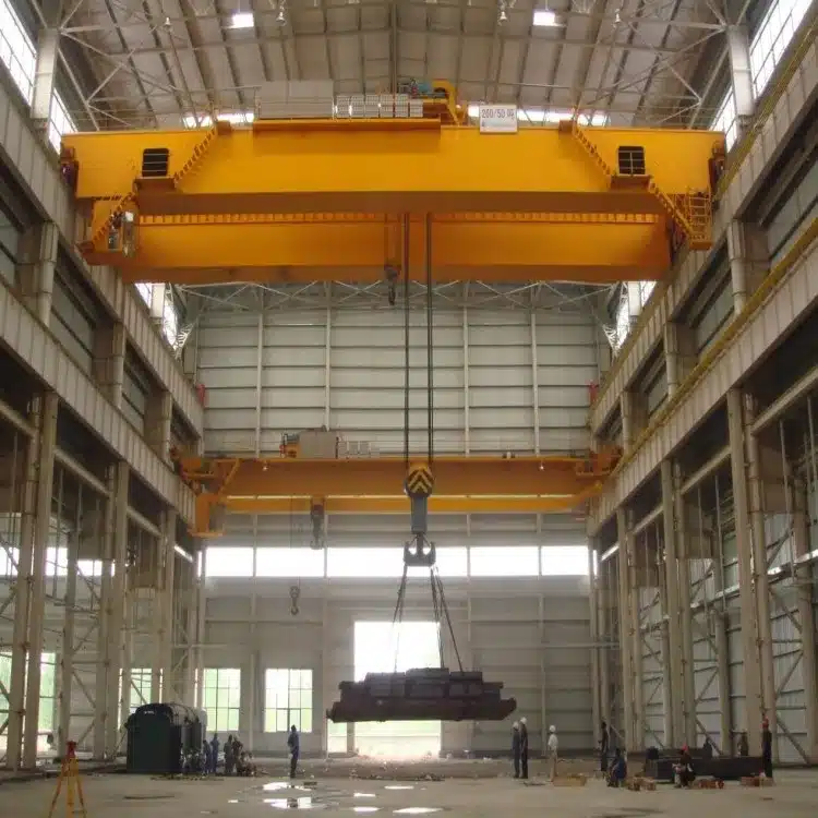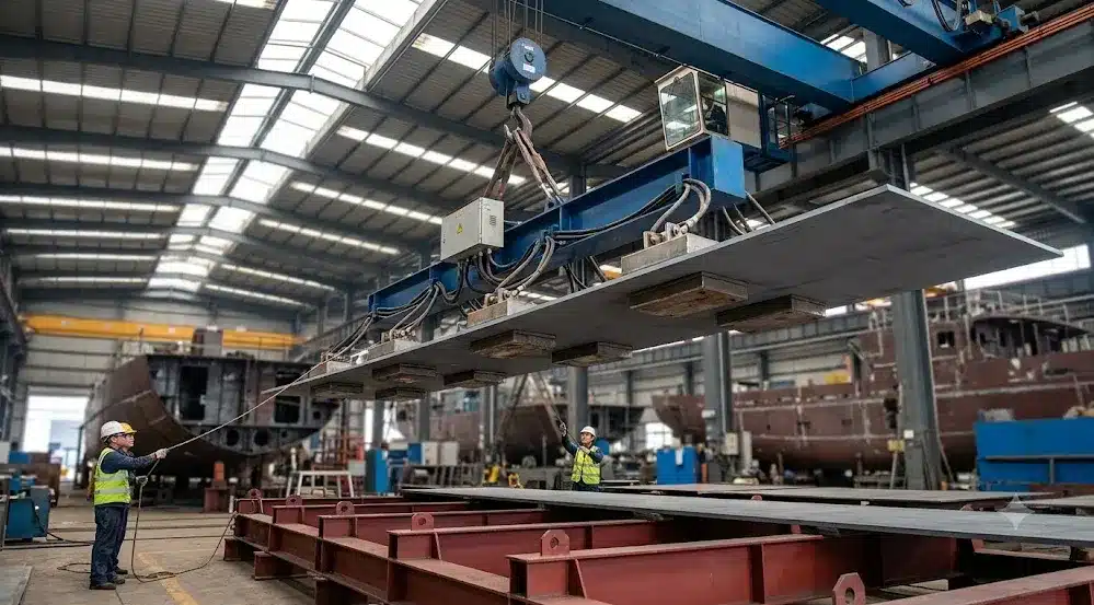


A tower crane had an accident on the construction site. One of the most common questions asked by the investigation team after entering the site was: Is there any record of the lifting weight, torque, wind speed, and rotation angle at that time? If there is only a closed black box and the data cannot be obtained, or only the driver has seen it by himself, the traceability of the accident becomes a wrangling with each other. This is exactly the embarrassment of traditional crane monitoring: something is installed, but no effective supervision is formed. The safety monitoring and management system that I want to talk about today is to solve this problem-it is not to add an “optional accessory” to the equipment, but the compliance bottom line of large-scale lifting machinery, the infrastructure for accident traceability, and the data entry for intelligent construction.

What does the traditional tower crane monitoring system look like? The background technology of patent CN202575791U is very straightforward: the original system consisted of a black box, a recorder, and a monitor, which could only communicate with each other inside the tower crane, and was only used by the driver for self-monitoring. , There is no access to an external communication network. The recorded data is mainly used in the post-mortem investigation stage after the accident, and usually does not play a supervisory role. What's more troublesome is that most of the cumulative operation records in the tower crane technical files are filled in by the user unit or the leasing unit, and the management department cannot verify the authenticity, leaving room for illegal operations.
People in the industry have experienced the consequences of this closed system. Overload, cable-stayed hanging, emergency stop and emergency return, these behaviors may only leave a string of data that no one can see in the stand-alone monitoring, and they will only be turned out when something happens. What a modern safety monitoring and management system has to do is to transmit these data in real time, so that drivers, site safety leaders, construction units, safety supervision departments, and leasing companies can all see the same set of operating conditions. In the words of patent CN202575791U, it is “open real-time dynamic supervision of tower cranes in an interconnected manner.”
Regulations are also pushing this matter away. Article 7.2 of TSG 51-2023 "Technical Regulations for the Safety of Lifting Machinery" clearly stipulates that metallurgical bridge cranes larger than 10t that have been shipped out of the factory before the issuance of this regulation shall be installed in accordance with the requirements of the regulations. Safety monitoring and management system. This is not a recommendation, it is mandatory. For newly built large-scale lifting machinery, Appendix a directly gives the directory that must be installed. In other words, for many devices, whether to install or not is no longer a multiple-choice question.
To figure out the regulatory requirements, we must first distinguish the division of labor between the three documents.
The first is TSG 51-2023, the safety technical specification for special equipment, which governs “which equipment must be installed” and “mandatory safety requirements”. Its appendix a "Catalogue of Large-scale Lifting Machinery for Installing Safety Monitoring and Management systems" lists very clearly: general-purpose bridge cranes above 200t, metallurgical bridge cranes greater than 10t, general-purpose gantry cranes above 100t, shipbuilding gantry cranes and bridge-building machines with unlimited parameters, ordinary tower cranes above 315t·m, Power station tower crane 315t·m or more, tire crane 100t or more, crawler crane 200t or more, gantry crane 60t or more, cable crane parameters are not limited, mast crane 100t or more. Note that the “above” in the catalog contains the number of copies.
The second is GB/T 28264-2017 “Safety Monitoring and Management System for Lifting Machinery”, the recommended national standard, which governs the general technical framework of "how to build the system". It specifies the composition, monitoring content, performance requirements and inspection requirements of the system, and is suitable for bridge, gate, mobile, tower, gate seat, cable, mast, bridge-building machine and ship lift machine. The comprehensive error of the system should not be greater than 5%, the hardware sampling period should not be greater than 100ms, the switching data should be stored sequentially when it changes, and the storage period of other data should not be greater than 2s, and the monitoring data for not less than 30 consecutive working days should be stored, and the video should not be less than 72 consecutive hours.
The third is GB/T 37366-2019 "Specification for Safety Monitoring System and Data Transmission of Tower Cranes", which is specifically for tower cranes and is finer than the general standard. It requires the system to collect lifting weight, lifting moment, lifting height, working range, boom elevation angle, wind speed, rotation angle, operating stroke, working time, cumulative working time, each working cycle, etc., the collection cycle is not greater than 100ms, and the continuous working day information of not less than the last 30 days is stored, audio and video storageNot less than 72h. A pre-warning and control signal output table is also given, and the alarm threshold and control signal output requirements are specified for the lifting moment, lifting weight, height, rotation, amplitude, wind speed, and operating stroke respectively.
The relationship between the three documents can be understood as follows: TSG pipe “must be installed”, GB/T 28264 pipe “general requirements”, GB/T 37366 pipe “tower crane special”. When making a plan, first check the TSG catalog to confirm whether the equipment is within the mandatory range, and then build the framework according to GB/T 28264, and then add the special requirements of GB/T 37366 to the tower crane.
A complete set of security monitoring and management system, according to the framework of GB/T 28264 and GB/T 37366, the functional units include: information acquisition unit, information processing unit, control output unit, information storage unit, information display unit, information output interface unit. When there is a need for remote monitoring, a remote transmission unit is added, an anti-collision unit is added during group tower operations, and an identification unit is added when there is a need for identification. One sentence is specified in the standard: This system is part of the electrical control system of lifting machinery and is not an independent product. This sentence is very important. It means that the system cannot be operated separately from the original electrical system of the crane, and the function of the original safety protection device should not be changed during installation.
The core of the hardware layer is the sensor. According to GB/T 28264 Tables 1 and 2, the sources of information that need to be collected include lifting weight limiter, lifting torque limiter, lifting height limiter, operating stroke limiter, amplitude limiter, skew limiter, interlock protection safety device, level sensor,Anti-wind anti-skid device, anemometer, rotation limiter, anti-collision device, overspeed protection device, etc. The monitoring parameters include lifting weight, lifting moment, lifting height/descending depth, operating stroke, amplitude, vehicle operating skew, level, wind speed, rotation angle, operating instructions, leg verticality, working time, cumulative working time, and work cycle.
Patent CN202575791U gives a specific sensor configuration example: the weight sensor is a pin-shaft load sensor, which is installed on the lifting mechanism of the tower crane; the wind speed sensor is arranged on the top of the rotating tower body; the amplitude sensor is equipped with the boom luffing mechanism; the angle sensor is equipped with a non-rotating main tower body.On the rotating mechanism between the rotating tower body; the height sensor is provided at the rear of the balance arm; the main controller and the liquid crystal display screen are provided in the driver's room; the wireless communication module is provided in the rotating tower body or in the driver's room. Although this configuration comes from a 2012 patent, the sensor layout logic still has reference value to this day.
In terms of communication layer, GB/T 28264 specifies four signal interface forms: passive switching, analog, pulse, and bus data. GB/T 37366 further gives the MODBUS-RTU communication protocol between the tower crane and the PLC, with a baud rate of 9600, data bit 8, stop bit 1, and even check; it communicates with the remote monitoring center based on TCP/IP, and the terminal initiates a connection to the monitoring center and sends a heartbeat regularly. There are more cutting-edge solutions in academic papers: Zhang Xiaoyuan et al. (2022) ZigBee wireless sensor network uses CC2530 chip and Cluster-Tree algorithm, Geng Donghong et al. (2026) big data solution uses 433MHz wireless module time division multiple access technology.
The platform layer is organized in a three-level structure: operation information is collected at the site level, remote monitoring is provided for managers at the local level, and all crane operation and fault information is monitored at the remote level. When there is a remote demand, the data is sent to the remote monitoring center or cloud platform through the remote transmission unit.
The functions can be broken into a chain: monitoring—alarm—recording—traceability—remote—video.
Real-time monitoring and display are the basis. GB/T 28264 requires the system to have the function of real-time recording of operating status and fault information, and to display working status and working parameters in graphics, images, charts and text. GB/T 37366 requires the tower crane to display the lifting weight, the percentage of lifting moment, the lifting height, the working range, the rotation angle, the magnification, the elevation angle of the boom, the operating stroke, etc., the display information is clearly visible under the lighting conditions in all directions.
Early warning, alarm and control output are the core values. GB/T 28264 stipulates that in addition to issuing an alarm when the system detects a fault, it should also have a preset stop control function according to the requirements; the alarm device can issue a clear sound and light alarm to the operator and personnel in the hazardous area. Table 2 of GB/T 37366 is more specific: sound and light alarms and control signals should be output when the lifting torque reaches 100% to 110% of the rated value, sound and light alarms should be output when they reach 90% to 95%, and prompts should be output when they reach 80%; lifting weight, height, rotation, amplitude,The wind speed and operating stroke also have corresponding alarm and control requirements. The engineering case of Geng Donghong et al. (2026) also gave three-level warning thresholds: normal structural stress [0,203)MPa, yellow warning [203,276) MPa, red warning [276,345) MPa; normal verticality of the tower [0,3)%, yellow[3,4)%, red[4,5); The wind speed is normal [0,9) m/s, yellow[9,12) m/s, red[12,15) m/s.
Data recording and historical traceability are the basis for accident liability. GB/T 28264 requires that the stored data or image information include the number and working time, keep all the collected information when the power is turned off or the power supply is interrupted, and store not less than 30 consecutive working days of monitoring data and not less than continuous 72h video data. GB/T 37366 requires the tower crane to store static parameters, work cycle information, real-time work information, and switch-on information, and record real-time work information at a frequency of 1/2s for regular storage. The A4.1.6.7 of TSG 51-2023 also requires the system to have a hardware interface open to the outside world, which can easily export recorded data.
Remote supervision and video linkage to send data out of the construction site. GB/T 37366 stipulates that when there are remote monitoring function requirements, the system should be able to communicate with the remote monitoring center; the audio and video monitoring system can include cameras, microphones, display screens, and storage devices. The video collects the initial position and final position information of the hanging point, and the audio should collect the driver's indoor audio, and the storage time is not less than 72h. The hook visualization device of Geng Donghong et al. (2026) also adds a rotatable camera and an automatic cleaning system, which increases the viewing angle coverage by 40% and the image clarity by 25dB.
On the technical route, there have been several obvious changes in the past ten years.
In the early days, field communication was mainly wired, but later wireless sensor networks entered the field of view. The ZigBee solution by Zhang Xiaoyuan et al. (2022) uses CC2530 as the core of the network hardware, USB and lithium batteries are jointly powered, and a distributed address allocation mechanism and Cluster-Tree algorithm are used to simplify node functions and reduce communication losses. Simulation experiments show that the average value of the acquisition error of the system is within 0.02V, and the maximum information packet loss rate is 1.81%. However, it should be noted that when the number of users reaches 200, the information packet loss rate is 75.4%, indicating that there are still bottlenecks in wireless solutions in large-scale concurrency scenarios.
The introduction of big data and AI has pushed the system from “recording” to “forecasting”. In the engineering case of Geng Donghong et al. (2026), the system uses Hadoop for distributed data storage, Spark Streaming for real-time analysis, isolated Forest algorithm to detect abnormal loads, and random forest model to predict structural stress trends. The early warning response time is less than 50ms, and the structural stress prediction error is less than 5%. This means that the system does not just wait for the parameters to exceed the limit before alerting, but can detect abnormal patterns in advance from historical data.
The collision prevention of group towers is just needed for the airport view of the tower. The scheme of Geng Donghong et al. (2026) uses a 433MHz wireless module to build an inter-tower crane communication network. Each tower crane acts as an independent node, adopts time division multiple access technology to avoid data congestion, and completes a status information exchange every 50ms. The Euclidean distance between the end points of the boom of the two machines is calculated through a three-dimensional space collision detection model.. Engineering data show that four tower cranes are dynamically isolated from the work area through this algorithm, and the accuracy rate of anti-collision early warning is 98.7%. During the entire project operation period, the incidence of safety accidents was reduced by 82%, the construction efficiency was increased by 12%, and the project construction period was 35 days in advance.
If you are in charge of a project, it is recommended to follow the following steps.
The first step is to check the catalog first. Refer to Appendix a of TSG 51-2023 to confirm whether your equipment is in the directory where the security monitoring and management system must be installed. Special attention: bridge cranes larger than 10t that have been shipped out of the factory and are in use must be installed before regular inspections. This step determines “whether to build or not”, not "how good to build".
The second step is to set the function according to the standard. Taking GB/T 28264 as the general framework, it ensures that the six functional units of information collection, processing, control output, storage, display, and output interface are complete; there are remote requirements and remote transmission, and group tower operations are collision-proof. The special requirements of GB/T 37366 are superimposed on the tower crane project. Don't miss the key indicators: the sampling period is not more than 100ms, the storage is not less than 30 days, the video is not less than 72h, the communication protocol is open to the outside world, and the management authority is graded.
The third step is to select the technology according to the scene. Stand-alone tower machines give priority to meeting the collection, display, alarm, and storage requirements of GB/T 37366; Group tower operations focus on anti-collision solutions, and 433MHz plus TDMA is the route verified by the project; if remote supervision is required, use TCP/IP plus 4G/5G to send data to the cloud platform; I want to send data to the cloud platform.For further data analysis, you can refer to the combination of Hadoop plus Spark Streaming plus isolated forest/random forest, but the actual data volume and operation and maintenance capabilities must be evaluated.
The fourth step is verification and operation and maintenance. Manufacturers' plans should be cross-verified, don't just look at the leaflet. Focus on checking several things: whether the data can be exported, whether the fault self-diagnosis is valid, whether the information is saved after the power failure, whether the alarm threshold meets the standards, and whether the communication protocol is open to the outside world. The patented scheme can refer to the structural design, but the 2012 technical scheme must be re-evaluated against the current standards. The installation of the system is not the end. During regular inspections, items such as management permissions, sampling cycle, storage time, and display clarity must be checked.
One last reminder: the value of a security monitoring and management system is not in the number of sensors, but in whether the data is really used. A system that meets the standards but no one looks at it is fundamentally different from a black box.
To this day, the crane safety monitoring and management system has passed the stage of ”do you want to install it or not". For equipment included in the TSG catalog, it is a mandatory requirement; for equipment not included, it is an infrastructure for incident traceability and intelligent management. The order in which it is built is very clear: first check the mandatory directory, then set the architecture according to the standard, and finally select the technology according to the scene. Standards are the bottom line, and it is the value of data that is truly used.
Next Article:Wire rope flaw detector: Before changing the rope, figure out what it can measure. »
24-Hour Service Hotline: 0717-6922999 WeChat: 13972023522 Email: technical@wtauserver.com Address: No.6 Gangcheng Road, Yichang Area, China (Hubei) Pilot Free Trade Zone
Copyright © 2026 Wtau Technology Co., Ltd. All Rights Reserved. ICP License No.: E ICP 12004023-1