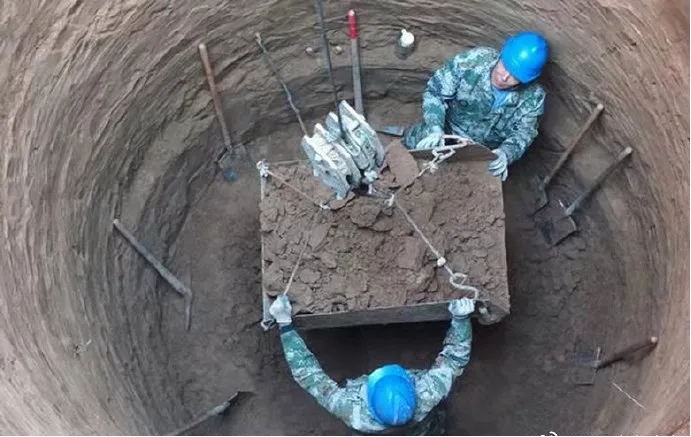
Product introduction:Suitable for acceptance measurement of excavated circular foundation pits for 110kV~750kV overhead transmission towers, max measurable pit depth: 10 m; adaptable to harsh field conditions including slopes over 35°, blocked sightlines, rainy, snowy and dusty environments.
Applicable purpose:
Application scenarios: 110kV~750kV overhead transmission line tower foundation digging foundation pit, cylindrical pile foundation foundation pit excavation acceptance measurement, suitable for the maximum depth of 10m foundation pit; can operate in complex working conditions with slope>35°, line of sight blocking, rain, snow and dust in the field.
Test content: Automatic measurement of the width of the foundation pit, the aperture of the floor, the depth of excavation, and the verticality of the whole section of the foundation pit; the measured data is benchmarked with national standards, and the pile depth and pile diameter error control is ≤±5mm, and the verticality deviation is ≤1/100.
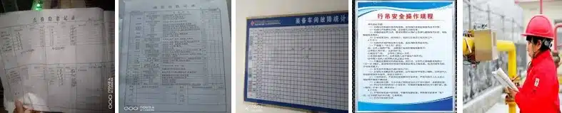
Extended use: acceptance and measurement of the geometric dimensions of cylindrical pile foundations and inner walls of small boreholes in construction projects, retention and archiving of point cloud data, and traceability of construction quality.
2. Product structure and performance characteristics
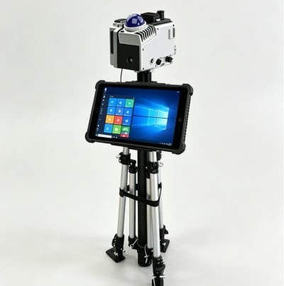
Structure composition of the whole machine:The whole machine consists of three modular components: a lidar measurement host, a hand-operated telescopic tripod, and a 10-inch touch data terminal (tablet), forming a closed-loop operation system of front-end scanning and acquisition, mid-end data processing, and back-end analysis and archiving.
Product performance characteristics:
Ultra-high measurement accuracy: plane and elevation measurement error ≤±5mm, point cloud density 100 points/㎡
Single-person efficient operation: the whole process is operated by one person, and the efficiency is more than 50% higher than that of traditional manual operation.
Weather-resistant operation all-weather: the host is IP66, dust-proof and waterproof, and works stably from -35℃ to 55℃
Real-time visualization: instant imaging of point clouds, on-site generation of three-dimensional models and measured values
Portable and lightweight: the total weight of the whole machine is ≤15kg, and the bracket can be folded for storage
Intelligent control and early warning: automatic reminder of exceeding the standard, one-click export of data to CAD/Excel
3. Main technical parameters
project
Technical indicators
Laser safety level
Level 1 (no harm to the human eye)
Scan field of view
360°×59° global scanning
Scan rate
200,000 points/second
Single point accuracy
1cm, resolution 2mm
Host protection
IP66 waterproof and dustproof, aviation aluminum body
Applicable foundation pit depth
0~10m, the range can be customized 0~50m
4. Standard configuration and options
Standard configuration:
PM-KJ300 lidar host×1 set
Hand-cranked telescopic three-legged lifting bracket×1 set
10-inch industrial touch tablet×1 set
Original lithium battery ×2 pieces, special charger×1 set
Storage bag, data cable, manual, test report
Permanent authorized version of the solution software